Hello everyone. So I am new to the rep-rap and 3D printing in general, but have wanted one for a few years now. I have slowly been collecting parts to piece together my own 3D printer. Being limited to a college budget, I have been looking for the cheapest solutions when possible, and came up with this simple way to make my stepper drivers. Not sure if this has been done before, but I didn't see anything after a quick search so I thought I would post my method.
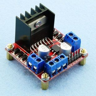
The circuit is a combination of the ST L297/298. While I'm sure the 297/8 is nothing new, I didn't feel like laying out my own PCB, and came up this simple way to piece together a driver from existing components. There are numerous L298 boards on ebay complete with heatsink, diodes, capacitors, and 5v regulators that look like this:
![]()
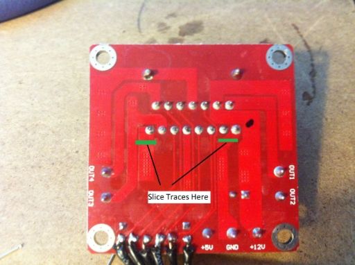
The downside to these boards is that they do not include a sense resistor for current control via a L297. However, this is fixed by simply cutting the correct traces and soldering in your own sense resistor.
![]()
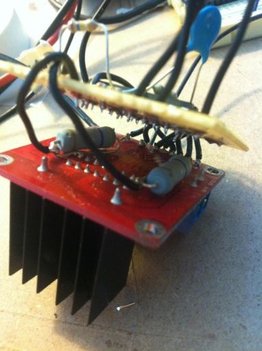
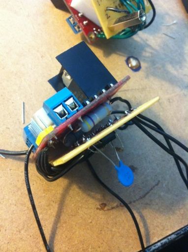
Then simply solder the L297 to another board, make the appropriate connections to the L298, add a resistor and capacitor to set the chopping frequency, two resistors as a voltage divider for the current sensing reference voltage, and wala! A quick and easy motor driver.
![]()
![]()
I was able to buy 5 pcs of the L298 board off ebay for ~$20, and 5pcs of the L297 for $1.29, for a grand total of $4.26 per driver (minus component/circuit board costs). Not too shabby!
I have tested the circuit at 12v, but plan to run it at 24v. The L297 can easily be set for full or half steps, but I believe it does not support microstepping. Regardless, this was a cheap and easy approach to a DIY stepper driver. Any comments/suggestions welcome
The circuit is a combination of the ST L297/298. While I'm sure the 297/8 is nothing new, I didn't feel like laying out my own PCB, and came up this simple way to piece together a driver from existing components. There are numerous L298 boards on ebay complete with heatsink, diodes, capacitors, and 5v regulators that look like this:
The downside to these boards is that they do not include a sense resistor for current control via a L297. However, this is fixed by simply cutting the correct traces and soldering in your own sense resistor.
Then simply solder the L297 to another board, make the appropriate connections to the L298, add a resistor and capacitor to set the chopping frequency, two resistors as a voltage divider for the current sensing reference voltage, and wala! A quick and easy motor driver.
I was able to buy 5 pcs of the L298 board off ebay for ~$20, and 5pcs of the L297 for $1.29, for a grand total of $4.26 per driver (minus component/circuit board costs). Not too shabby!
I have tested the circuit at 12v, but plan to run it at 24v. The L297 can easily be set for full or half steps, but I believe it does not support microstepping. Regardless, this was a cheap and easy approach to a DIY stepper driver. Any comments/suggestions welcome