Sure, its pretty straight forward. However, the L298 is also limited to 2 amps. If you want to drive a larger stepper motor, you will need a H Bridge with a higher current rating, or according to the datasheet you can put multiple L298's in parrallel for higher output current (i.e. you can get up to 3 amps driving each coil with its own 298).
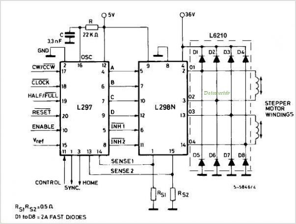
Here is a diagram of the connections between the L297/298 for reference:
![]()
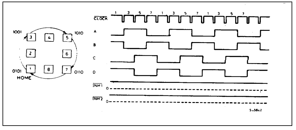
The L297 performs two actions. First it translates step and direction input into the correct sequence to drive the H Bride (L298). If you look at this timing diagram:
![]()
The clock signal represents a "step" command from your microcontroller, and the ABCD lines represent the translated output from the L297 to the L298. Its possible to use a microcontroller to control the ABCD lines directly, but it just complicates things.
Second, and more importantly, the L297 controls the current flowing through the motor coils. Essentially, the coils have a very low resistance, so you would have to use a very low voltage power supply if you were to drive them directly. For example, I have some stepper motors rated at 2.3 volts and .7 amps, which means the coil resistance is likely 3.29 ohms(3.2/.7). If I were to drive them with 12 volts directly, the current would be 3.65 Amps (12/3.29), way too high and the motor would almost certainly overheat and die.
So why not just use a low voltage power supply? The motor coils also have significant inductance, which simply put means that when a voltage is applied, the current will lag the voltage/ it will take time for the current to reach its maximum value. This is an issue, as the current, not voltage, is responsible for creating the magnetic field that drives the motor. The solution to this is to use a high voltage supply, so that the the current increases more quickly. Then, by sensing the current going through the motor, the motor current is shut off, or "chopped", when the current reaches a set value.
The job of the sense resistors in the schematic are to monitor the current flowing through the motor, and then the L297 performs the chopping action, essentially limiting the current going through the coils.
This is a simplified explanation, and I'm a mechanical engineer not an electrical, but hope it clears things up a bit. The connections from the 297 to the 298 are relatively easy, if you have any questions about how you would connect everything I'll try to answer them
Here is a diagram of the connections between the L297/298 for reference:
The L297 performs two actions. First it translates step and direction input into the correct sequence to drive the H Bride (L298). If you look at this timing diagram:
The clock signal represents a "step" command from your microcontroller, and the ABCD lines represent the translated output from the L297 to the L298. Its possible to use a microcontroller to control the ABCD lines directly, but it just complicates things.
Second, and more importantly, the L297 controls the current flowing through the motor coils. Essentially, the coils have a very low resistance, so you would have to use a very low voltage power supply if you were to drive them directly. For example, I have some stepper motors rated at 2.3 volts and .7 amps, which means the coil resistance is likely 3.29 ohms(3.2/.7). If I were to drive them with 12 volts directly, the current would be 3.65 Amps (12/3.29), way too high and the motor would almost certainly overheat and die.
So why not just use a low voltage power supply? The motor coils also have significant inductance, which simply put means that when a voltage is applied, the current will lag the voltage/ it will take time for the current to reach its maximum value. This is an issue, as the current, not voltage, is responsible for creating the magnetic field that drives the motor. The solution to this is to use a high voltage supply, so that the the current increases more quickly. Then, by sensing the current going through the motor, the motor current is shut off, or "chopped", when the current reaches a set value.
The job of the sense resistors in the schematic are to monitor the current flowing through the motor, and then the L297 performs the chopping action, essentially limiting the current going through the coils.
This is a simplified explanation, and I'm a mechanical engineer not an electrical, but hope it clears things up a bit. The connections from the 297 to the 298 are relatively easy, if you have any questions about how you would connect everything I'll try to answer them